


همه محصولات
-
 برونو نازسنتوممنون از کمک و حمایت مداوم شما در ارائه محصولات با کیفیت بالا و مقرون به صرفه به ما.
 -
 احسان سالماريپاسخ سریع و رفتار حرفه ای باعث می شود که همکاری ما راحت تر انجام شود!
General Electric DS200DCFBG1B DC بازخورد منبع بازخورد توربین بحرانی و برنامه های درایو


| محل منبع | ایالات متحده آمریکا |
|---|---|
| نام تجاری | GE |
| گواهی | COO |
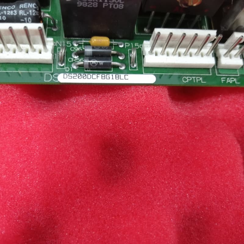
| شماره مدل | DS200DCFBG1B |
| مقدار حداقل تعداد سفارش | 1 |
| قیمت | $1800 |
| زمان تحویل | 5-7 روز |
| شرایط پرداخت | t/t |
| قابلیت ارائه | 999 |
جزئیات محصول
| نام | General Electric DS200DCFBG1B DC بازخورد منبع بازخورد توربین بحرانی و برنامه های درایو | شناسه محصول | DS200DCFBG1B |
|---|---|---|---|
| سری | مارک V | ضمانت | 1 سال |
| عمق/طول خالص محصول | 330 میلی متر | ارتفاع خالص محصول | 200 میلی متر |
| وزن خالص محصول | 2 کیلوگرم | عرض خالص محصول | 100 میلی متر |
| برجسته کردن | صفحه بازخورد منبع برق DC SW6,هیئت بازخورد 12 پرنده,38 VAC/115 VAC Input Power Supply Board (بورد برق ورودی VAC) |
||
توضیحات محصول
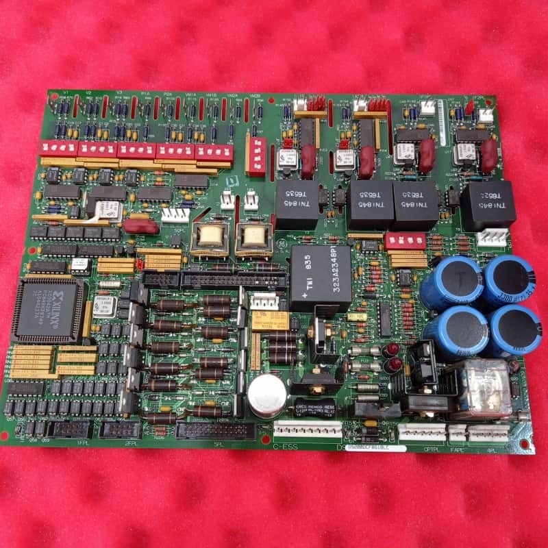
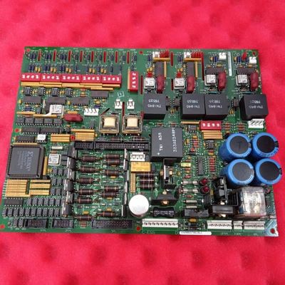
جنرال الکتریک DS200DCFBG1B صفحه بازخورد منبع برق ثابت توربین و برنامه های کاربردی محرک
توضیحات محصول:
جنرال الکتریکDS200DCFBG1Bیک تخته بازخورد منبع برق DC است که برای کاربردهای مهم توربین و محرک، از جمله سری EX2000، DC2000 و AC2000 طراحی شده است. به عنوان یک مرکز مدیریت و نظارت بر برق مرکزی عمل می کند،تبدیل قدرت ورودی از یک ترانسفورماتور قدرت کنترل به ولتاژ های مختلف DC تنظیم شده برای کار با سیستم محرک و فن های محفظه.
ویژگی های کلیدی:
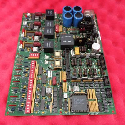
نقش اصلی هیئت مدیره تولید و توزیع چندین منبع برق سطح کنترل از جمله +5V، ±15V و ±24VDC است. فراتر از تبدیل قدرت،این یکپارچه مدارهای نظارت پیچیده ای را که پارامترهای اساسی سیستم مانند جریان و ولتاژ آرماتور را ردیابی می کنند.، جریان میدان موتور و ولتاژ خط AC و توالی فاز. همچنین شامل مدارهای راننده برای ژنراتورهای پالس دروازه SCR میدان موتور است.
یکی از ویژگی های تعریف کننده DS200DCFBG1B استفاده از مدارهای ولتاژ کنترل شده نوسان دهنده (VCO) است. این مدارهای ولتاژ ورودی آنالوگ بحرانی را از ولتاژ پل SCR تبدیل می کنند.ولتاژ پل خروجی، و سیگنال های میلی ولت از میدان و آرماتور به سیگنال های فرکانس متناسب (0-500 kHz) تغییر می کنند.این سیگنال های فرکانس دیجیتال سپس به SDCC یا LDCC کنترل صفحه اصلی برای پردازش منتقل می شود، ارائه بازخورد قابل اعتماد در مورد وضعیت عملیاتی موتور.
این صفحه از طریق دوازده جمپر و هفت سوئیچ DIP بسیار قابل تنظیم است ، که امکان گزینه های خاص مشتری را فراهم می کند ، اگرچه این گزینه ها معمولاً در کارخانه تنظیم می شوند.شامل ویژگی های قوی تشخیص و حفاظت استوضعیت منبع تغذیه +5VDC توسط سیگنال / PSEN نشان داده می شود که می تواند ریست میکروپروسسور را در کارت کنترل در صورت تنظیم ولتاژ غیر منظم انجام دهد.صفحه توسط فیوز محافظت می شود (FU1، FU2، FU3) برای خروجی های برق خود، با شاخص های بصری روشن ✓LEDs CR51 و CR55 برای فیوز های DC و یک چراغ نیون LT1 برای فیوز AC ✓ برای شناسایی سریع نقص.
![]()
محصولات توصیه شده